Packet Tracer – Connect a Router to a LAN
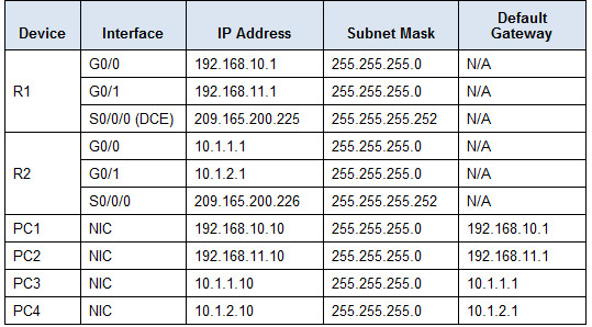
Addressing Table
Objectives
Part 1: Display Router Information
Part 2: Configure Router Interfaces
Part 3: Verify the Configuration
Background
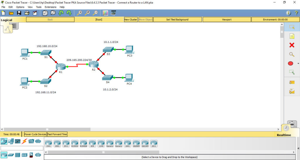
In this activity, you will use various show commands to display the current state of the router. You will then use the Addressing Table to configure router Ethernet interfaces. Finally, you will use commands to verify and test your configurations.
Note: The routers in this activity are partially configured. Some of the configurations are not covered in this course, but are provided to assist you in using verification commands.
Part 1: Display Router Information
Step 1: Display interface information on R1.
Note: Click a device and then click the CLI tab to access the command line directly. The console password is cisco. The privileged EXEC password is class.
a. Which command displays the statistics for all interfaces configured on a router?
R1#show interfaces
b. Which command displays the information about the Serial 0/0/0 interface only?
R1#show interfaces serial 0/0/0
c. Enter the command to display the statistics for the Serial 0/0/0 interface on R1 and answer the following questions:
1) What is the IP address configured on R1?
2) What is the bandwidth on the Serial 0/0/0 interface?
Instructions
R1#show interfaces serial 0/0/0
R1#show interfaces serial 0/0/0
Serial0/0/0 is up, line protocol is up (connected)
Hardware is HD64570
Internet address is 209.165.200.225/30
MTU 1500 bytes, BW 1544 Kbit, DLY 20000 usec,
reliability 255/255, txload 1/255, rxload 1/255
Encapsulation HDLC, loopback not set, keepalive set (10 sec)
Last input never, output never, output hang never
Last clearing of “show interface” counters never
Input queue: 0/75/0 (size/max/drops); Total output drops: 0
Queueing strategy: weighted fair
Output queue: 0/1000/64/0 (size/max total/threshold/drops)
Conversations 0/0/256 (active/max active/max total)
Reserved Conversations 0/0 (allocated/max allocated)
Available Bandwidth 1158 kilobits/sec
5 minute input rate 64 bits/sec, 0 packets/sec
5 minute output rate 67 bits/sec, 0 packets/sec
43 packets input, 2540 bytes, 0 no buffer
Received 0 broadcasts, 0 runts, 0 giants, 0 throttles
0 input errors, 0 CRC, 0 frame, 0 overrun, 0 ignored, 0 abort
43 packets output, 2560 bytes, 0 underruns
0 output errors, 0 collisions, 1 interface resets
0 output buffer failures, 0 output buffers swapped out
0 carrier transitions
DCD=up DSR=up DTR=up RTS=up CTS=up
d. Enter the command to display the statistics for the GigabitEthernet 0/0 interface and answer the following questions:
1) What is the IP address on R1? –> unassigned
2) What is the MAC address of the GigabitEthernet 0/0 interface?
3) What is the bandwidth on the GigabitEthernet 0/0 interface?
Instructions
R1#show interfaces gigabitEthernet 0/0
GigabitEthernet0/0 is administratively down, line protocol is down (disabled)
Hardware is CN Gigabit Ethernet, address is 000d.bd6c.7d01 (bia 000d.bd6c.7d01)
MTU 1500 bytes, BW 1000000 Kbit, DLY 10 usec,
reliability 255/255, txload 1/255, rxload 1/255
Encapsulation ARPA, loopback not set
Keepalive set (10 sec)
Full-duplex, 100Mb/s, media type is RJ45
output flow-control is unsupported, input flow-control is unsupported
ARP type: ARPA, ARP Timeout 04:00:00,
Last input 00:00:08, output 00:00:05, output hang never
Last clearing of “show interface” counters never
Input queue: 0/75/0 (size/max/drops); Total output drops: 0
Queueing strategy: fifo
Output queue :0/40 (size/max)
5 minute input rate 0 bits/sec, 0 packets/sec
5 minute output rate 0 bits/sec, 0 packets/sec
0 packets input, 0 bytes, 0 no buffer
Received 0 broadcasts, 0 runts, 0 giants, 0 throttles
0 input errors, 0 CRC, 0 frame, 0 overrun, 0 ignored, 0 abort
0 watchdog, 1017 multicast, 0 pause input
0 input packets with dribble condition detected
0 packets output, 0 bytes, 0 underruns
0 output errors, 0 collisions, 2 interface resets
0 unknown protocol drops
0 babbles, 0 late collision, 0 deferred
0 lost carrier, 0 no carrier
0 output buffer failures, 0 output buffers swapped out
Step 2: Display a summary list of the interfaces on R1.
a. Which command displays a brief summary of the current interfaces, statuses, and IP addresses assigned to them?
R1#show ip interface brief
Interface IP-Address OK? Method Status Protocol
GigabitEthernet0/0 unassigned YES unset administratively down down
GigabitEthernet0/1 unassigned YES unset administratively down down
Serial0/0/0 209.165.200.225 YES manual up up
Serial0/0/1 unassigned YES unset administratively down down
FastEthernet0/1/0 unassigned YES unset up down
FastEthernet0/1/1 unassigned YES unset up down
FastEthernet0/1/2 unassigned YES unset up down
FastEthernet0/1/3 unassigned YES unset up down
Vlan1 unassigned YES unset administratively down down
b. Enter the command on each router and answer the following questions:
1) How many serial interfaces are there on R1 and R2? –> 2 interface
2) How many Ethernet interfaces are there on R1 and R2? —> R1: 6 interface ; R2: 2 nterface
3) Are all the Ethernet interfaces on R1 the same? If no, explain the difference(s).
Step 3: Display the routing table on R1.
a. What command displays the content of the routing table?
R1#show ip route
b. Enter the command on R1 and answer the following questions:
1) How many connected routes are there (uses the C code)?
2) Which route is listed?
R1#show ip route
Codes: L – local, C – connected, S – static, R – RIP, M – mobile, B – BGP
D – EIGRP, EX – EIGRP external, O – OSPF, IA – OSPF inter area
N1 – OSPF NSSA external type 1, N2 – OSPF NSSA external type 2
E1 – OSPF external type 1, E2 – OSPF external type 2, E – EGP
i – IS-IS, L1 – IS-IS level-1, L2 – IS-IS level-2, ia – IS-IS inter area
* – candidate default, U – per-user static route, o – ODR
P – periodic downloaded static routeGateway of last resort is not set
209.165.200.0/24 is variably subnetted, 2 subnets, 2 masks
C 209.165.200.224/30 is directly connected, Serial0/0/0
L 209.165.200.225/32 is directly connected, Serial0/0/0
3) How does a router handle a packet destined for a network that is not listed in the routing table?
A router will only send packets to a network listed in the routing table. If a network is not listed, the packet will be dropped.
Part 2: Configure Router Interfaces
Step 1: Configure the GigabitEthernet 0/0 interface on R1.
a. Enter the following commands to address and activate the GigabitEthernet 0/0 interface on R1:
R1(config)# interface gigabitethernet 0/0
R1(config-if)# ip address 192.168.10.1 255.255.255.0
R1(config-if)# no shutdown
%LINK-5-CHANGED: Interface GigabitEthernet0/0, changed state to up
%LINEPROTO-5-UPDOWN: Line protocol on Interface GigabitEthernet0/0, changed state to up
b. It is good practice to configure a description for each interface to help document the network information. Configure an interface description indicating to which device it is connected.
R1(config-if)# description LAN connection to S1
c. R1 should now be able to ping PC1.
R1(config-if)# end
%SYS-5-CONFIG_I: Configured from console by console
R1# ping 192.168.10.10
Type escape sequence to abort.
Sending 5, 100-byte ICMP Echos to 192.168.10.10, timeout is 2 seconds:
.!!!!
Success rate is 80 percent (4/5), round-trip min/avg/max = 0/2/8 ms
Step 2: Configure the remaining Gigabit Ethernet Interfaces on R1 and R2.
a. Use the information in the Addressing Table to finish the interface configurations for R1 and R2. For each interface, do the following:
1) Enter the IP address and activate the interface.
2) Configure an appropriate description.
b. Verify interface configurations.
Step 3: Back up the configurations to NVRAM.
Save the configuration files on both routers to NVRAM. What command did you use?
Instructions
R1(config)#interface gigabitEthernet 0/1
R1(config-if)#ip address 192.168.11.1 255.255.255.0
R1(config-if)#no shutdown
R1(config-if)#description LAN connection to S2
R1(config-if)#exit
R1(config)#exit
R1#ping 192.168.11.10
Type escape sequence to abort.
Sending 5, 100-byte ICMP Echos to 192.168.11.10, timeout is 2 seconds:
.!!!!
Success rate is 80 percent (4/5), round-trip min/avg/max = 0/0/0 ms
R1#copy running-config startup-config
Part 3: Verify the Configuration
Step 1: Use verification commands to check your interface configurations.
a. Use the show ip interface brief command on both R1 and R2 to quickly verify that the interfaces are configured with the correct IP address and active.
How many interfaces on R1 and R2 are configured with IP addresses and in the “up” and “up” state?
What part of the interface configuration is NOT displayed in the command output?
What commands can you use to verify this part of the configuration?
b. Use the show ip route command on both R1 and R2 to view the current routing tables and answer the following questions:
1) How many connected routes (uses the C code) do you see on each router?
2) How many EIGRP routes (uses the D code) do you see on each router?
3) If the router knows all the routes in the network, then the number of connected routes and dynamically learned routes (EIGRP) should equal the total number of LANs and WANs. How many LANs and WANs are in the topology?
4) Does this number match the number of C and D routes shown in the routing table?
Note: If your answer is “no”, then you are missing a required configuration. Review the steps in Part 2.
Step 2: Test end-to-end connectivity across the network.
You should now be able to ping from any PC to any other PC on the network. In addition, you should be able to ping the active interfaces on the routers. For example, the following should tests should be successful:
· From the command line on PC1, ping PC4.
· From the command line on R2, ping PC2.
Note: For simplicity in this activity, the switches are not configured; you will not be able to ping them.
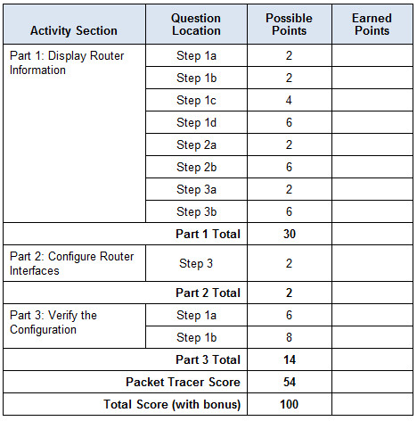
Suggested Scoring Rubric